Flying Drone DIY, Part III: Assembling and Tuning
Intro
This publication describes the assembly and tuning of a drone whose design and configuration were discussed in previous posts.
The process is relatively straightforward yet still technically sophisticated —
some domain-specific knowledge is required to complete it successfully.
The ArduPilot team did an excellent job documenting the process, but there remains
some room to bridge practical gaps.
Hardware part
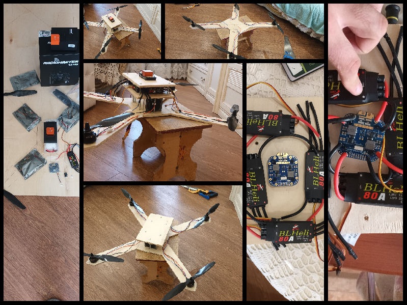
Soldering connectors
ESCs and motors come without pre-soldered connectors, so you have to
solder them yourself.
During soldering, I faced issues bonding the solder to the metal
surfaces of the connectors. Using colophony (rosin flux) and several
careful attempts, I achieved satisfactory results.
My soldering skills are basic — you might find superior techniques
through additional research or practice.
Soldering PDB and dealing with EMI
The next stage involves soldering ESCs to the power distribution board (PDB).
Similar soldering challenges arise here, requiring accuracy to avoid
overheating the board or damaging traces and nearby components.
Another issue was adapting thick ESC cables to the PDB. The chosen ESCs
support up to 80 A of current and use thick 12 AWG wires.
Consequently, the selected PDB should support at least 320 A (by specification),
but the soldering holes were only half as large as needed. Adjusting wire
diameter or using additional connectors are both viable solutions.
Most PDBs have an open design. Considering how much current flows through them, it is important to protect them from accidental contact and from rain or moisture.
Another challenge is electromagnetic interference (EMI). Current flowing through
wires creates an electromagnetic field that can affect nearby signal lines.
The higher the current, the stronger the interference.
Therefore, it is crucial to keep the battery, PDB, flight controller, and
RC receiver physically separated. Aluminum foil can also help provide shielding,
especially for high-frequency interference. In my setup, I placed a foil layer
between the FC and the PDB.
Engines: CW vs CCW
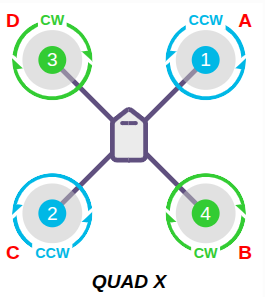
When using ArduPilot, pay close attention to the motor order. ArduPilot expects a specific motor sequence for each frame type — see the official documentation for details.
The order depends on the direction of motor rotation — clockwise (CW)
or counterclockwise (CCW). This is done to balance the torque forces;
otherwise, the drone would rotate uncontrollably. CW and CCW motors
are arranged in pairs along each axis.
The motor’s direction can be reversed by swapping any two of the three
wires connected to the ESC.
Both motor and propeller directions matter. Propellers are designed for specific rotational directions, and each produces thrust only when installed correctly. Always check that each motor spins in the intended direction with the correct propeller.
The Pixhawk board has a numbered MAIN OUT panel for connecting ESCs. Refer to the ArduPilot documentation for correct motor numbering.
Flight controller: RC setup
The radio receiver also arrived disassembled. Using documentation, identify the correct pins for your configuration and solder the wires properly.
I had to order a new cable to match the Pixhawk connectors, which use JST-GH connectors (6 pins, 2 mm). Pay attention to the exact connector type — several models exist under the JST prefix.
Another point to be aware of is wire colouring. Although JST-GH connectors are standard, colour coding is not guaranteed. In my case, black did not indicate ground and red did not indicate power. Always consult documentation before connecting wires, or you risk damaging components.
Also, note the pin orientation — Pixhawk’s printed labels can be misleading. I initially confused pin 1 with pin 6. Using a multimeter check and familiarising yourself with JST-GH layouts will help avoid such mistakes.
EMI mitigation is also important. The primary EMI sources are the battery,
power lines (PDB, ESCs), and the radio receiver. The flight controller
should be positioned as far as possible from them.
In this configuration, it was mounted as a second layer above the battery,
with an additional aluminium foil layer for protection.
Flight controller: connecting ESCs
ESCs can be powered in two ways — directly from the PDB or through the FC
via a BEC.
Since in my setup they were powered directly from the PDB, it was necessary
to disable the BEC’s power supply by removing the red wire from the connector
going to the FC.
All ESCs were connected to the MAIN OUT ports of the FC as described above.
Handmade frame
For the first version, I chose a handmade frame. Since it’s an R&D project, the configuration is not final, and the frame must allow for extensions and reconfiguration. I used particleboard as an affordable material, though plastic would likely be a better choice — lighter, durable, and easier to drill and cut.
The main question was: what frame thickness and arm length can support 2 kg of thrust per axis?
To answer this, I solved a classical cantilever beam bending problem (with ChatGPT’s help). However, I was unsure about my material’s stiffness coefficient, and the real-world results showed that the frame lacked sufficient rigidity. I solved this by adding a second frame layer — the rigidity then became adequate with a safety margin.
Another key aspect is centring the mass. Otherwise, you will have to compensate for imbalance in software by adjusting motor thrust, which is undesirable. In my case, this was straightforward — the battery accounts for about 85% of the total weight, so placing it in the centre was a natural choice. EMI concerns also dictated the layout, with sensitive parts arranged on separate layers.
A production-ready design should integrate all these considerations elegantly. More ergonomic R&D is planned for version 2 of the drone.
Importance of motor KV
| KV (rpm/V) | Typical Propellers | Battery Type | Drone Type / Application | Characteristics |
|---|---|---|---|---|
| < 400 KV | 18" – 32" | 6S–12S | Heavy-lift, long-range, industrial drones | Very high torque, large propellers, ultra-efficient at low RPM. Designed for long-endurance flights carrying 2–10 kg. |
| 400–600 KV | 15" – 18" | 6S–8S | Medium-lift, aerial photography, mapping | Balanced between efficiency and thrust. Ideal for 20–40 min endurance. |
| 600–900 KV | 12" – 15" | 4S–6S | General-purpose or filming drones | Good torque but higher consumption. Common for 5–8 kg drones. |
| 900–1200 KV | 9" – 12" | 3S–4S | FPV / Freestyle drones | High RPM, responsive, efficient but noisy. |
| 1200–1800 KV | 5" – 8" | 3S–4S | Racing drones | Extremely fast, short flight time (3–7 min). |
| > 1800 KV | 3" – 6" | 2S–4S | Mini / training drones | Very high speed, low efficiency, high noise. |
Selecting the right combination of motor KV, propellers, and battery voltage is essential for achieving the desired performance. The table above can serve as a practical reference.
Choosing the right ESC
The maximum current drawn by the selected motor is 28 A. However, short bursts can reach up to 1.8 × 28 A = 50 A, and peaks up to 2.5 × 28 A = 70 A. Therefore, the ESC should handle at least 70 A, or 60 A with appropriate burst protection (burst-rated ESCs exist for this purpose).
Such high currents require thicker wires. The ESC wires supplied were twice as thick as the motor and PDB wires, creating a mismatch — something worth considering during the design stage.
Software part
Below is the full list of configuration and calibration steps performed during the flight controller setup. Step 15 (Telemetry setup) has been postponed since the GCS modem is currently unavailable.
Configuration steps
| No | Step | Status | Notes |
|---|---|---|---|
| 1 | Firmware installation | ✅ | ArduCopter firmware successfully installed |
| 2 | Frame type selection | ✅ | Configured as Quad / X type |
| 3 | Accelerometer calibration | ✅ | Completed via Mission Planner |
| 4 | RC transmitter calibration | ✅ | Radiomaster TX16S + CRSF receiver |
| 5 | Compass calibration | ✅ | Performed after final assembly |
| 6 | ESC and motor calibration | ✅ | ESCs configured on PWM |
| 7 | Motor and propeller direction check | ⏳ | Pending — to verify propeller rotation |
| 8 | Flight mode setup | ✅ | Stabilize / AltHold / Loiter configured |
| 9 | Failsafe configuration | ✅ | Radio, battery, and GCS failsafes configured |
| 10 | Power module and battery levels | ✅ | Voltage-only mode set for Cube Orange HV PM |
| 11 | OSD configuration | ➖ | Not used (no camera installed) |
| 12 | Voltage/current sensor calibration | ✅ | Completed; current via ADC not measured |
| 13 | AutoTune or manual PID tuning | ⬜ | Planned after first hover test |
| 14 | Logging configuration | ⏳ | Postponed — logs cannot yet be read from device |
| 15 | Telemetry (GCS) setup | ⏳ | Postponed — GCS modem not available |
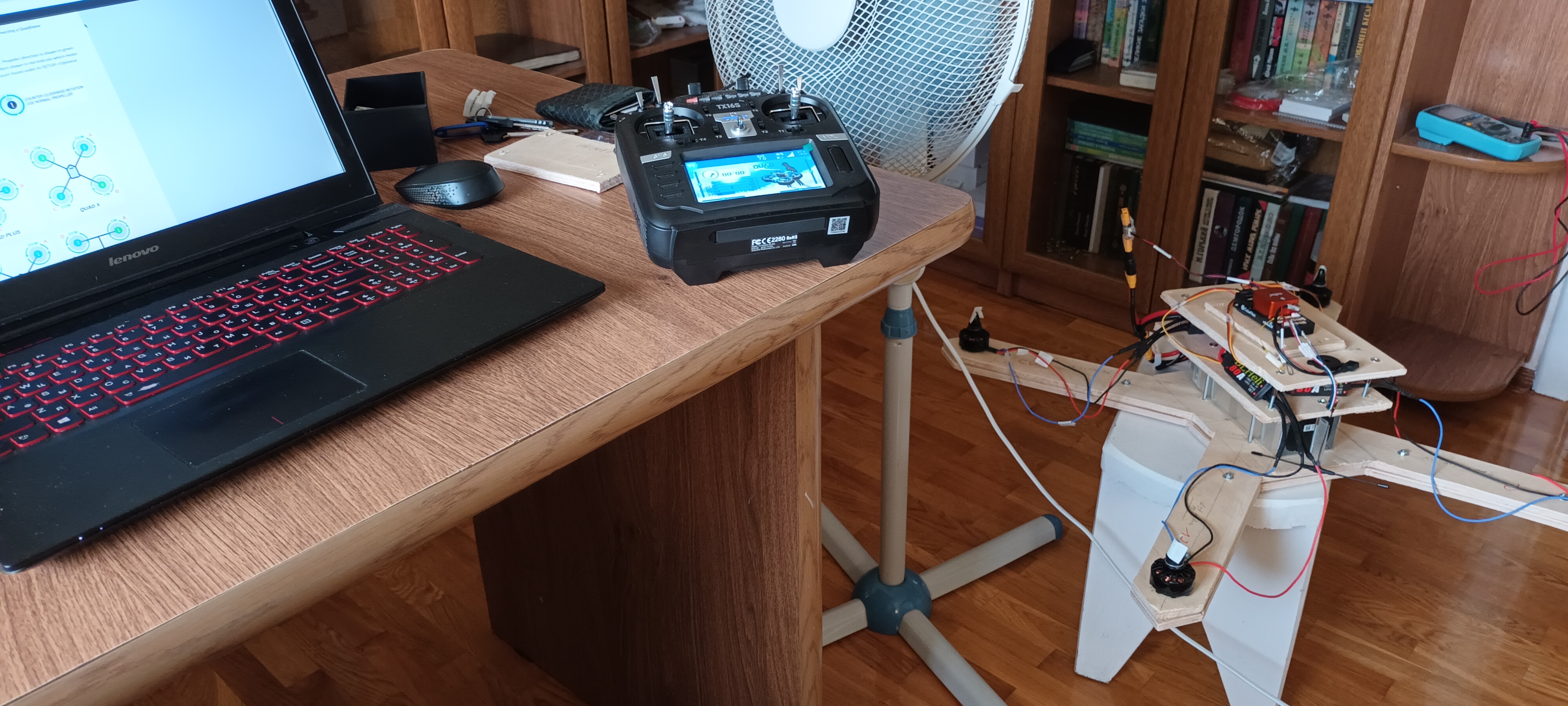
Flashing firmware and choosing the frame
FC is connected to PC over mini usb. ArduPilot team provides
MissionPlanner -- software which allows to configure software
part of the copter over GUI as well as to plan automatic missions.
As a first steps you have to choose your type of vehicle and
frame.
For more details check
official documentation.
Accelerometer calibration
You have to put your copter on all 6 posiible positions. It is
important to keep it in the one position for a few seconds until
the confirmation to let FC correctly get&write params.
For more details check
official documentation.
Compass calibration
You have to rotate your copter in different directions until
receiving a sound confirmation from your FC about the end of
configuration.
For more details check
official documentation.
Radio calibration
Radio controls calibration is neccessary to let FC understanding
which values are max and min of the passing signal. It has several
tricky nuances you have to pay attention to.
For more details check
official documentation.
Also in my case of ELRS I have to buy & install extra module
for my RC transmitter to support ELRS. This step also requires
updating firmware on the pult. Another interesting point is
option to adjust controlling signals on the pult over software
for more precise control of drone movement.
ESC & motors calibration
Electronic speed controllers also have to be configured to run motors according to percent of power passed to them. Modern protocols doesn't require it, but basic one like PWM still need this.
Till this moment the chain RC transmitter -> RC receiver -> FC
should be already installed and tested. One particular issue which
remains hidden at start is a safety switch.
Safety switch is a hardware protector from passing the power to
the motoros. Carbon propellers and running motors could severely
damage your tissues and muscles, so indeed such kind of protector
is neccessary.
In my case safety switch was not provided neither by a separate wire
or port on Pixhawk board, so it was always enabled on and prevented
calibration of ESCs. You have to check GPS cable for it and even
if you do not use GPS, you have to install the cable to use this
button -- long press on it makes safety switch off. Power will
come to ESC and you will hear nice sound from them.
For more details check
official documentation
Motor direction and prop check
As was described in hardware part each motor should take the right position and spin in the right direction. Get a small speed over RC transmitter or using special test in MissionPlanner will help you to confirm the right direction of motors
Not only motors, but propellers as well should rotate in the right direction. Check them and see under which direction, clockwise or counter clockwise, it will grasp the maximum air. It will give you clear understanding on which motor each of them should be installed.
For more details check official documentation
Flight mode setup
Operating the drone requires to virtuosly giving a different power on each of its motors. This orchestration is automotize by Ardupilot. In addition to it sevel flight modes are designed to give a proper UX from operating over RC transmitter.
RC transmitter sticks could be and should be assigned to at least some of this flight modes. A few the most important ones at start are stabilize and land.
For more details check official documentation
Failsafe configuration
"Copter has a number of failsafe mechanisms to ease vehicle
recovery/prevent wandering in the event that vehicle control
is lost. "
(c) official docs
Power module and battery levels
You have to setup expected voltage and current of your battery and several thresholds to let flight contoroller (FC) know when to trigger special event assigned to each of them, e.g. land the copter on minimum level of the battery.
The voltage and current doesn't come to measurement sensors as is,
but over voltage divider. This values should be restored back to
original through multiplying on special coefficient.
I setup this values for voltage, but for current I hadn't succeed
yet with current -- likely because of lack of current sensor itself.
For more details check official documentation
5th trial flight on minimum gas
The minmum gas been used for better control of the drone. With more flight experience gas could be rised up to the maximum without (much) danger for the garden and others objects around.
The next steps would be to solve flaws discovered after trial launches and develop 2nd generation of copter.
| Version | Brief purpose | Business intent / Technical task / Tech components |
|---|---|---|
| V1 | Minimal RC drone Assembly and verification of base platform |
|
| V2 | Video (FPV) and telemetry Adding live video feedback for operator |
|
| V3 | ML integration On-board video processing |
|
| V4 | Autonomy and analysis Navigation, SLAM, and target filtering |
|
The whole technical docs where is allmost all research is written down is avaliable by this link.
A few related posts:
Flying Drone DIY, part V: custom autopilot programs -- improving computer vision of drone
Flying Drone DIY, Part IV: custom autopilot programs
Flying drone DIY, part II: configuration for the 1st version
Flying drone DIY, part I: discovery phase
Broad vs narrow specialisation.