Electronics tech notes, part II: recover manufactory machine
Executive summary
Work of the motherboard had been fixed. It isn't tested yet on
the machine in the production facility, however all key
signals are valid.
In this case the life of the machine has been extended, business
value produced by work of a master on this machine has been remained
and business saved 500k - 3 000k rubles on ordering a new machine.
This machine is a 35 years old Soviet Russian CNC milling machine,
quite good for its time. The machine has reached the end of its
service life many years ago, but it is still at work and with
minimal investments continues work and produces business value.
The issue
The master of the machine reported he had issue with it. When he input
values which exceeds some upper bound, a required number didn't
appear on CNC display. Further investigation shown two motherboards
were responsible for this.
What this motherboards do is convert number from a binary format to
a binary-decimal format. Obviously by some reason they stopped to
do it correctly. Organization was able to replace this motherboards
immediately by spare parts, but there wasn't more equal motherboards
and it was important to repair broken ones to extend the life of
this machine in the future.
How to fix it?
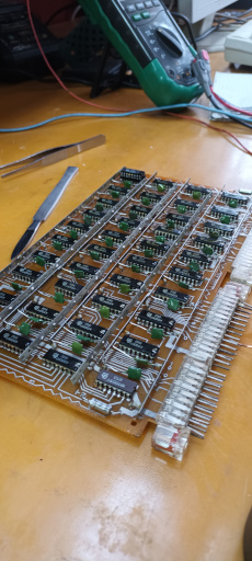
This motherboard consists from 40 identical microschemes КР155ПР7 or west analog 74185 (actually, 74185 was first, Texas Instruments become a trend setter and it would be right to call КР155 seria an analog). What it does is converting a binary number from input to a binary-decimal number on the output. It means we can pass a binary number on the input of the microscheme and check does it have a valid number on the output. This microscheme support 32 possible numbers, but checking just one number on each microscheme should be enough to evaluate does it broken or not.
I like the idea to start debugging from the input or the output of the motherboard.
Another way recommended by my colleague is to trace signal between pins of each microscheme - if they conduct current between each other, likely microscheme is broken.
Motherboard's coordinate system
This 40 microschemes are positioned in matrix where we have a scale
from A to L at an one side and from 1 to 4 at the another side.
Input pins are split one two panel. The right one has prefix 'A',
the left one goes without prefix.
Even numbers of pins goes from one side of the motherboard, odd
numbers goes on the another side of the motherboad.
КР155ПР7 general overview
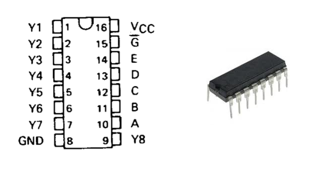
The first we have to take a look on a power supply and a ground pins. They are under number 16 and 8. It is common to majority if not to say all microschemes to have pins intended for this. What is specific for this microscheme, this is to have 15 pins connected to the ground.
Working voltage is near 5V where is 5.6V is an upper bound.
From the right side we have pins for inputs, from the left side - pins for outputs. However on principal circuits schemes (at least Soviet Russians schemes), inputs are drawn on the left and outputs on the right which might bring some mess in a further work.
For our work only 5 pins from input (10-14) and 5 pins from output are important (Y1-Y5).
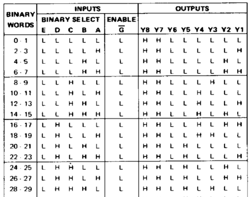
This table shows all possible combinations of signals on input and output pins and how they should depend on each other. Validity of a microscheme means it should give such values on this set of signals on input pins.
What are logical 1 and logical 0?
How to encode 1 or 0 on a hardware level? Obviously as a signal
existence or a lack of it. However hands-on experience with
electronics shown several nuances.
Logical zero is not a lack of a current, but some low voltage
current which microscheme designers are agreed on. Unfortunately
they do not agreed on worldwide level which exactly voltage
range to consider as a low signal aka logical zero. Therefore
this voltage range become unique for each microscheme. For this one
it is near 0.4V.
If existence of a current can mean both logical 0 and logical 1,
how to distinguish one from another? We also agreed on a some
voltage range which will be interpreted as a logical one. For
this microscheme this is a near 5V. However this is also a data
which vary from microscheme to microscheme of different series
and may be even types. I even met microschemes which have logical
1 defined by different voltage ranges for two different pins -
one microscheme on one pin has one voltage is interpreted as
a logical 1, on another pin - another voltage is interpreted as
a logical one.
Free input voltage
When you just put a voltage on a microscheme, the voltage on
its pins is called free input voltage. It also has its own
voltage range and by different microschemes are threated
differently.
For this microscheme it is considered as a logical one. I had
to build a separate circuit to test it and confirm its work.
What else left?
My first experience with КР155ПР7 shown some values on the
output, but the voltage was near zero - much less even of
logical zero. However changes in voltages weren't random, they
have their own logic. If I would take different voltage range
for a logical one and a logical zero, the microscheme gives
right results!
Further investigation shown I should check results on the
output over the 1kOm - 5kOm resistance connected to a power
supply. When it was done, I got my 5v as a logical 1 and 0.4v
as a logical 0.
It is a common for microschemes series built by this design
(TTL chips), but it was not clear for me at the beginning.
A few related publications:
Electronics tech notes, part I: repair a power supply
https://gelassen.github.io/blog/2024/01/21/electronics-tech-notes-part-1-getting-started.html
Broad vs Narrow specialization
https://gelassen.github.io/blog/2021/02/27/broad-vs-narrow-specialisation.html
Principles behind my work
https://gelassen.github.io/blog/2020/06/05/how-we-work.html