Electronics tech notes, part I: getting started
Intro
Past two months I have been diving into electronics and this publication
opens a seria of notes on this topic.
It covers repairing 'Siemens SITOP power 20' power supply and based
on this explains basic foundation elements and principles of
electrics and electronics.
Disclaimer: standards which regulates electric voltage in common
wires and some other things are different from region to region.
In this publication I will use standards used by Russia and the
rest post-Soviet countries.
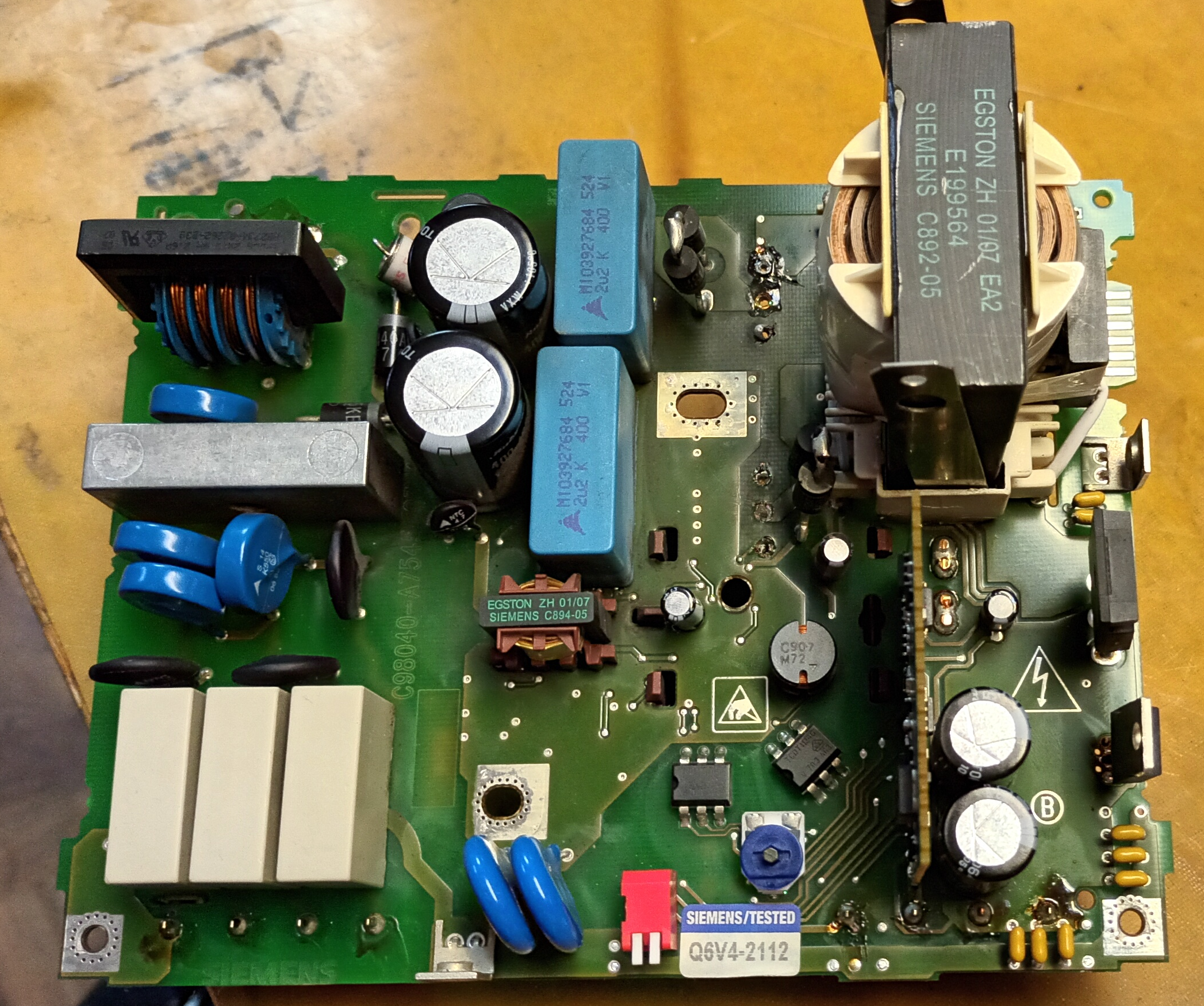
First overview
First overview of the power supply didn't show any damages caused
by fire or blasts. People who brought this to our laboratory claimed
there were some blast, fire and smoke inside.
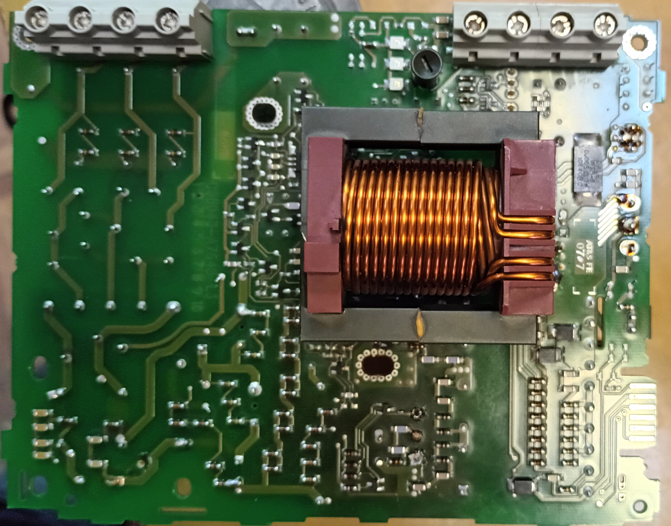
Next step was checking key elements of the power supply on current resistance with help of a multimeter. It also didn't show any issues.
This power supply has sophisticated architecture, so not everything was obvious. The next step was to draw a circuit of it.
Power supply input and 3 phase current from a common electric plug
I started from the input. It has place for four cables - three of them represent different phases, the last one is a neutral.
Why do we get 3 phase AC current?
Physics behind electricity transmission makes passing DC current
on long distances unprofitable due big losses on hitting. AC current
has been using instead.
After some period of experimentations engineers worldwide came
to the concept of three phase electricity. It has several
advantages, where the most relevant for my aims is it makes
DC current afterwards more smooth (do you notice short gaps
between periods on the image below?)
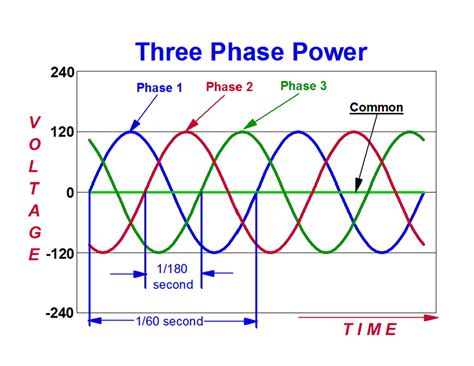
How does it work?
Three phase AC power source transmit high voltage current over wires. Near end user there is a transformer which converts high voltage current to a specific voltage current required by end user. For apartments it is 220V/280V. This voltage you can get from a plug in your apartment.
Physics behind current and electricity in general
Electricity is caused by movement of 'free' electrons and electron
holes. By electron hole implies lack of electron which should be
at that place. The absence of an electron behave itself in
current as a particle. This together with due to the
concentration of electrons and the concentration of their absence
have impact on the charge, the term 'electronic hole' is used.
Electrons (n) and electronic holes (p) during movement in the
conductor which is called p-n junction.
Concentration of electrons or of their holes creates a charge,
charge create a voltage which may produce current.
Capacitors: stabilize current
Capacitors are often used to stabilize a current. Either by spike
at current's source or due spike in circuits, e.g. voltage drop when
transistor just has been opened, current within circuit will
fluctuate, which will have negative impact on stable work of the
device. Capacitors are used to solve this issue.
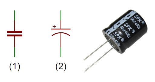
Capacitors are not traced by multimeter. Multimeter might show once a resistance caused by some potential which is still charged by a capacitor, but in general it should not show anything. If a capacitor is traced, it means it has too big leakage and should be replaced.
Thermistors: the first line of protection
Thermistors are elements which increase its/resistance (decrease current through them) when
temperature of element has reached some threshold. However, another
type thermistors are more popular - NTC. They decrease its
resistance since some threshold. They are connected in parallel. In
this circuit they are used as a first line of the protection.
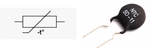
Looks like they give some delay of current growth on the first launch of the power supply to prevent high current damage the rest elements of the circuit (in this case - capacitors).
Varistors: the second line of protection
Varistors uses the same principle like thermistors, but if
thermistors respond on change in a temperature, varistors reacts on
changes in voltage. If the high voltage current comes over input,
varistor get shorted.
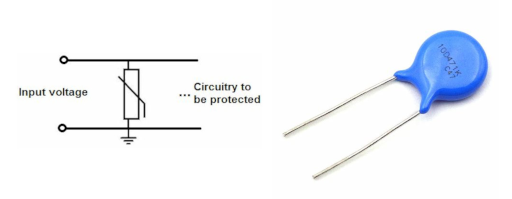
It is interesting to note the first electrode of the varistor is one wire (one phase) of AC source and another electrode is connected to another wire (another phase) of AC source. When spike in electricity source appears, it will be channeled to a different wire which phase is shifted (in other words its current wave is lower and has a capacity to be risen up by extra current which came by another wire). Such spikes are expected to be extremely short and in such cases it will work (and energy would not be wasted as it might be if a varistor will be shorted to the ground)
Varistors and thermistors should not be traced - provide current between their electrodes. If they do, it means they are broken.
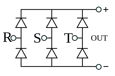
Diode bridge or 3 phase Larionov's rectifier: rectify current
Diode bridge is used to rectify current. You noticed your power
supplies are connected to AC's source, but most of our devices
requires DC. Diode bridge is what is usually used to convert
AC to DC.
This gif shows how does it work. Each semiconductor chain is either open on a high part of current's wave or on a low part of the wave which gives a stable current as an output.
Because of AC is usually supplied by 3-phase scheme, instead of diode bridge Larionov's rectifier is used. It has connections for all three wires of AC input.
Filter
After capacitors, first two lines of protection and bridge the next two
elements on circuit are filters. At the first glance they look as
a transformer, but a transformer either has at least two windings or
two input and two output pins.
Filters are used to clear out some frequency range from a signal or
from a current at this case. The type (ferrite or iron) of the core
in each of this two filters is different and has a limit on how big
frequency it is possible to pass through. Each of them filters
different types of noise.
Arrestor: the third line of protection
Arrestor is a specific variation of a gas tube charger. This is two
electrodes in a short distance between each other in a box full of
an air or a special gas. When a current reaches specific threshold
electricity start to go through the arrestor. Arrestors are used
to cope extra voltage due its spike in a circuit. In this scheme it
is a 3rd line of protection.
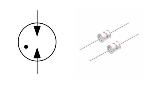
Arrestor's one electrode should be grounded which gave me an idea they are bipolar, but actually it is not necessary, however polarity of a current is important. EPCOS manufacturer produces arrestors for positive current (in red box) and negative current (in blue box). In the case of this circuit instead of ground the 2nd electrode goes to a plus of a capacitor.
In this circuit it is connected in parallel which means they become enabled only in voltage spikes, at the rest of work they do not participate in current flow.
Arrestors also should not be traced. If they do, it means they are broken.
There is no full guarantee to prevent your electronics break down due voltage jumps
As you see the first overview doesn't show any visible damage to the power supply. The next step is to check with help of multimeter a resistance between each key element of the circuit - it will show an element is working. However such checks have shown all elements of this multilines protection from voltages jumps are all fine, they are working. It means they didn't help to protect the power supply from breakage in this specific case.
Induction coil: increase current
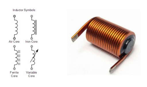
Main current after two filters goes through suppressors to a induction coil. Induction coil increases current.
Large capacitors one-by-one: a reservoir for an energy
Besides their role as a filter capacitors conntected together
serve as a reservoir for an energy, because connected
device might drastically increase its demand in an energy in a short
period of time, but the power supply without such capacitors is
not able to provide it. It is also interesting to note capacitors's
role as a bypass filter.
This ones are large and able to filter high spikes in a current, but
due its physical characteristics have their own induction and ESR,
which might be an issue in some use cases.
How to select an appropriate capacitor for input voltage stabilization
Capacitors in parallel
Because of big capacitors are targeted to filter large noise, they
are not good to deal with a low noise. That's why smaller capacitors
are usually set up in parallel to filter the rest range of noises.
Often they are also done from a different material like ceramic
which has insignificant induction and the smallest ESR which is
perfect for final endpoint which consumes the energy.
It is also worth to note about 'decoupling' nature of a capacitor.
Because of own resistances and inductions in circuit together with
some fractions of noises a plain circuit unable to supply a pure
current to sensitive elements like chips. A capacitors put down
near the chip solves this issue
Transformer: convert high current to a required current
![]()
Why do we need it?
Power supplies are not only rectify current (AC to DC conversion), but also convert voltage and current power from input values to values required by device they are used for. Transformer does this.
How it works?
Movement of charged particles creates magnetic field, changes
in the magnetic field produces inductive current. If you wind
wire around a conductive core, where which end you connect to
a plus of a current source and another end connect to a minus of
the current source, changes in polarity of current will produce
changes in the magnetic field. This alternating magnetic field
will produce a current in the conductive core around winding.
The conductive core is circled on itself and has another wire
is winded no another segment of it. Using the same principle
electricity produced by current on the 1st winding collected by
the 2nd winding.
When you change thickness of wire and number of wire wrapping
circles, you increase or decrease current it goes through this.
That's a point of a transformer: get highest voltage as an input
and over this two windings convert to a current of a lower
voltage. With voltage of the current we change the power of the
current too.
Use case
This circuit has a couple of transformers. I am not sure about
intent of the first one, but the second one is used for
downgrade current.
It is interesting to note power supplies design is intended to
separate parts of the circuit under the high voltage from
parts of the circuit under low voltage. Just one more level of
protection.
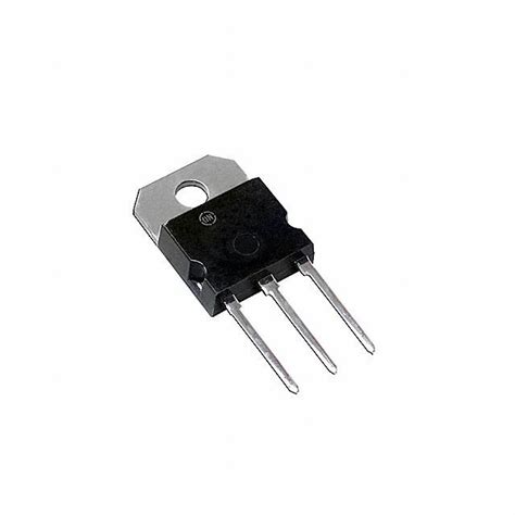
Transistor: open or close different segments of circuit
![]()
The power of transistors is ability to conduct or stop current through them by sending small electricity signal to it. Worth to note the power current also varies and it is regulated by the same signal.
Transistors are made from conductive materials which have different type of conductance - positive (p) or negative (n). By putting together two types of conductive material - positive and negative - they become semi isolated from each other, they still able to conduct current, but under special conditions. That's why they are called semiconductors.
Such condition is an electricity signal which comes on a 3rd electrode of a transistor which is called base or gate. This signal opens a transistors to conduct current and varies the power of it.
The most commonly used transistors are which exploits three p-n transmissions - n-p-n or p-n-p, - where the left part is an input (anode), the right part is an output (cathode) and the part in the middle is a base or gate. p gate is controlled by positive current, n gate is controlled by a negative current.
The complete theory behind its work is very interesting and several american physicists got a Nobel prize for its explanation in the beginning of 50-x in XX century, so you might continue learn more by read their papers or a specialized literature.
Darlington transistors
![]()
This circuits has one here. It seems it is used for amplifying current. This publication on electronics.stackexchange.com has good explanation of how it works.
Pair of diodes
They looks as a transistor, but actually they are different element and they have to be tested differently. It is important to check each element specification.
Pulse-width modulation (PWM) controller
It is a key element of modern power supplies. It is used for
increase efficiency of its work. I am not ready yet to explain to
you how it works, but this element is what had been broken in this
power supply.
After I had checked a datasheet on this element, I got an understanding
what it expects as a input and what we should expect on the output.
Such black-box testing gave me result - this microscheme doesn't
work as an expected. I request a new one and after replacement we
will see if power supply will get back to work.
Optocoupler
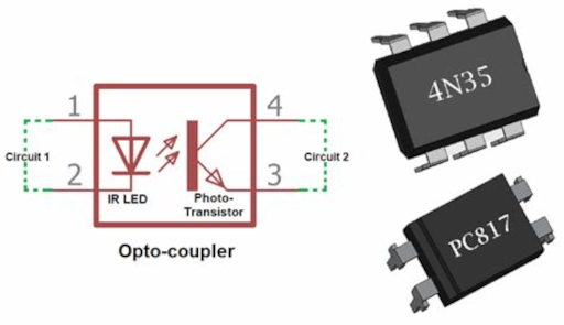
This power supply has option to work in different modes. Switching between this modes is done with help of a couple of optocouplers. I am amazed by this components and here is why.
They have inside a light emission element and a photo diode which is activated by light. By putting different light elements and photo diodes you can separate two different circuits under different (!) voltages by non-galvanic (!) way. Why is it important?
It creates an extra level or protection between different parts of the circuit. Those of you who have background in software engineering know how important to encapsulate different pieces of logic and how bad is when an abstraction leaks. If such issues arises on the software level, you can imagine what kind of issues might appear on the hardware level. Optocouplers are one extra way to protect you from them.
Conclusion
At least one cause of power supply's breakage has been found.
Will new PWD controller fix the issue or not will be clear when
ordered component will be delivered and installed.
Repairing this power supply gave me a lot of new knowledge
regarding electronics and how power supplies works in general:
from AC sources to capacitors to smooth a current -> from capacitors
to a bridge to rectify/convert AC to DC -> somewhere in the middle
thermistors and varistors are connected in parallel as extra level
of protection -> from bridge to a couple of filters to clear current
from unrequired frequencies/noises -> through inductive coil to
paired capacitors of different type and size to amplify the voltage
and filter different types of noises -> from capacitors to a
transformer to eventual convert current to a required power and
voltage.
Circuit might not be traced in the normal mode, but could be traced
in the diode mode, because some transistor opens the gate and start
to provide current. It brings extra challenges in checking both
a circuit and an electronic component on the circuit.
A few related publications:
Broad vs Narrow specialization
https://gelassen.github.io/blog/2021/02/27/broad-vs-narrow-specialisation.html
Principles behind my work
https://gelassen.github.io/blog/2020/06/05/how-we-work.html
Flying drone DIY
https://gelassen.github.io/blog/2023/03/19/case-study-flying-drone-diy.html